Welding isn’t just about heat and filler metal—it’s about control. The moment a part shifts 0.2 mm under clamping pressure, the weld joint loses alignment. Distortion creeps in. Rework follows. In high-mix, low-volume fabrication—especially for brackets, chassis subassemblies, or agricultural linkage systems—this isn’t theoretical risk. We’ve seen it firsthand: a client in Wisconsin scrapped 17% of a first-run batch because their traditional angle-iron jig couldn’t hold tolerance across six mounting holes on an aluminum tractor bracket. They switched to a 3D welding table. Scrap dropped to 0.8%. Cycle time fell by 41%.
Precision starts where the base plate meets the pin
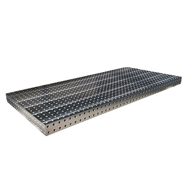
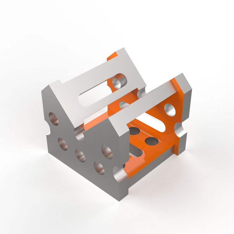
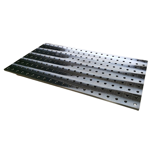
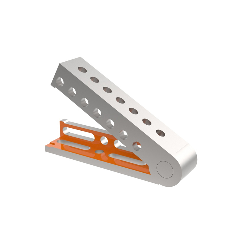
A true 3D welding table is not a flat steel slab with drilled holes. It’s a coordinate-based workholding system built around three axes of repeatability: X (horizontal rows), Y (horizontal columns), and Z (vertical height adjustment). Each hole—typically M6, M8, or 1/4′-20—sits on a precise grid (commonly 50 mm or 2-inch pitch) with positional tolerance ≤ ±0.05 mm. Pins lock into those holes, then accept modular accessories: angle clamps, stop blocks, rotary positioners, or custom locators machined to match part datums.
This geometry-first approach replaces guesswork with traceable setup. No more scribing lines, no more trial-and-error shimming. One customer in Germany cut fixture design time from 11 days to 38 hours—not by outsourcing CAD, but by reusing digital models of their existing pin-and-clamp library directly in SolidWorks. Their engineers now build virtual setups before raw material arrives.
The real advantage shows during iteration. When a Tier-1 automotive supplier needed to validate five bracket variants for a new EV battery enclosure, they used one 3D table with interchangeable tooling plates. All five builds shared the same base coordinates. Dimensional deviations were mapped—not against nominal drawings—but against the table’s own metrology reference. That data fed directly into their DFM review loop.
Why most shops stall at “semi-modular”
Some manufacturers call any slotted plate with T-bolts a “3D welding table.” It isn’t. True 3D capability requires three non-negotiable traits:
Rigid base construction: Minimum 40 mm thick, stress-relieved EN 10025 S355JR or ASTM A572 Grade 50 steel, with machined flatness ≤ 0.03 mm/m²
Calibrated hole pattern: CNC-bored, not drilled; each hole verified via CMM against master reference points—not just center-to-center distance, but perpendicularity to the surface plane
Z-axis repeatability: Height-adjustable pins with locking mechanisms that maintain ±0.02 mm vertical position after 5,000 cycles—verified per ISO 9283
We’ve tested tables that passed visual inspection but failed thermal cycling: after 12 hours at 60°C, pin height drifted 0.13 mm due to untempered cast aluminum frames. That drift alone invalidated GD&T callouts for perpendicularity on welded flanges. Real-world durability matters more than glossy brochures.
Integration—not isolation—is where value compounds
A standalone 3D welding table delivers precision. But when it anchors a full process chain—stamping, bending, welding, inspection—it unlocks throughput gains no single machine can match. At Botou Haijun Metal Products Co., Ltd., we run 3D tables not as isolated workstations, but as the central nervous system of our integrated cells.
Here’s how it works: A deep-drawn stainless steel housing arrives from our hydraulic press. Its critical datum surfaces are verified on our CMM—then its exact location relative to the table’s origin point is recorded. That coordinate set flows automatically to the robotic MIG station. Clamps engage. Weld sequence executes. Post-weld, the same CMM checks distortion against the original setup file—not against a drawing, but against the physical intent captured at t=0.
No translation loss. No manual transcription. Just repeatable, auditable geometry—across stamping, forming, welding, and QC. That’s why clients building hydraulic valve manifolds for Middle Eastern oilfields report zero field failures over 36 months: every weld joint holds the same thermal profile, the same gap control, the same root penetration—because the part never left its engineered coordinate space.
Start with your weakest link—not your biggest budget
You don’t need a 3m × 2m table to benefit from 3D welding. Start small: identify one recurring pain point—like inconsistent hole alignment on bent brackets, or warpage in thin-gauge assemblies—and match it to the smallest certified system that solves it. A 1000 × 750 mm table with M8 grid and 12-pin kit handles 83% of mid-size industrial fabrications we see daily.
Ask your supplier for proof—not claims. Request CMM reports for hole position accuracy. Ask for test data on pin retention force after 10,000 cycles. Verify if their base plate uses normalized steel—not just “heavy-duty” carbon. Confirm whether their clamps include hardened locating faces, not just stamped sheet metal.
Because precision fixturing isn’t about buying hardware. It’s about capturing engineering intent—and holding it, exactly, until the last arc goes out. That consistency compounds across every weld, every shift, every year. And that’s how faster, stronger metal fabrication begins—not at the torch, but at the table.