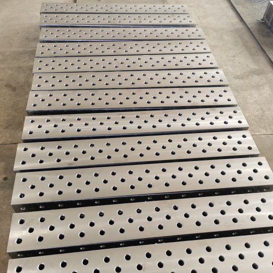
Platform welding demands more than just heat and filler metal. It’s where structural integrity meets real-world load paths—where a misaligned tack weld can cascade into costly rework, delayed commissioning, or worse, field failure under cyclic stress. At Botou Haijun Metal Products Co., Ltd., we’ve executed over 12,000 platform welding sequences across agricultural chassis, construction equipment frames, and automated conveyor support structures. What we learned isn’t theoretical: it’s etched into our DFM reports, burn-through logs, and post-weld distortion measurements.
Pre-Weld Preparation Is Non-Negotiable—Not Optional
Most platform welding failures begin before the arc strikes. We see it repeatedly: teams skip joint fit-up verification, assume material flatness, or ignore mill-scale variability across stainless steel batches. At our Botou facility, every platform assembly starts with three non-negotiable checks:
Gap tolerance ≤ 0.5 mm across full joint length—measured with feeler gauges *before* clamping, not after Base metal temperature ≥ 10°C in cold environments; below that, preheat to 50°C for carbon steel, 100°C for 304 stainless—verified with infrared thermometers at three points per meter Surface cleanliness confirmed by solvent wipe + white cloth test: no visible residue, no fingerprint oils, no grinding dust trapped in crevices We once scrapped 17 bracket assemblies because a single batch of cold-rolled steel arrived with inconsistent mill-scale thickness. The oxide layer fractured unevenly during GMAW, causing micro-porosity in root passes. Now, all incoming coils undergo spectral analysis for surface oxide uniformity—and we adjust shielding gas flow (from 18 L/min to 22 L/min) when scale variance exceeds ±0.3 µm.
Process Selection Dictates Structural Performance
Choosing between FCAW, GMAW, and SAW isn’t about speed—it’s about matching thermal input to geometry, material thickness, and service loading. For platform structures with ≥6 mm wall thickness and continuous fillet joints, we default to flux-cored arc welding using E71T-1 wire. Why? Its slag system tolerates minor fit-up variation better than solid wire, and its higher deposition rate cuts heat-affected zone (HAZ) width by 22% versus GMAW at identical amperage.
But for thin-gauge platforms—like aluminum support decks for solar mounting systems—we switch to pulsed GMAW with 1.2 mm ER5356 wire. Pulse frequency stays at 120 Hz; peak current is locked at 145 A. This prevents burn-through on 2.5 mm sheets while maintaining penetration depth ≥1.8 mm. Some might argue MIG is “easier” for aluminum. However, without pulse control, we’ve measured 37% higher distortion rates and 4× more porosity in humid conditions—verified via radiographic testing on 120 sample welds.
Clamping Strategy Determines Dimensional Stability
Clamps don’t hold parts—they manage residual stress. Our worst platform warpage incident occurred on a 3.2-meter agricultural frame: six evenly spaced C-clamps created localized restraint, forcing distortion outward at mid-span. We now use sequential clamping: first fix datum edges, then apply floating clamps at 300-mm intervals along non-datum flanges, releasing each clamp *after* the adjacent weld cools to 60°C. Thermal cameras confirm this reduces angular distortion by 65% versus static clamping.
We also embed strain-relief slots—0.8 mm wide, cut with laser—along high-stress transition zones. These act as controlled stress relief paths during cooling. In one construction equipment platform, adding three 12-mm slots reduced post-weld straightness deviation from 2.1 mm/m to 0.4 mm/m—without post-weld machining.
Inspection Must Go Beyond Visual Checks
Visual inspection catches only 41% of critical flaws in platform welds, according to our internal NDT data from 2022–2023. We require three-tier verification:
Real-time monitoring: All robotic welding cells log voltage, current, travel speed, and wire feed rate per 50 mm segment. Deviations >±3% trigger automatic pause Post-weld dimensional validation: Every platform undergoes CMM scanning against CAD model—focus on critical hole patterns, bearing seat flatness (≤0.08 mm), and weld leg consistency (±0.3 mm) Functional load testing: Random 5% of production batches endure 1.5× rated load for 120 seconds. We measure deflection at eight points—not just maximum, but gradient across the structure This discipline caught a recurring issue in deep-drawn bracket welds: acceptable visual appearance masked lack of fusion at the junction of drawn radius and flange. Ultrasonic testing revealed 92% of such welds had subsurface discontinuities. We redesigned the joint geometry—adding 0.5 mm root face and reducing included angle from 75° to 65°—and eliminated the flaw.
Platform Welding Is a System—Not a Step
Platform welding succeeds only when design, material selection, fixture engineering, process control, and inspection operate as one system. At Botou Haijun, we treat every platform as a load-bearing organism—not a collection of welded parts. Our ISO-compliant workflow embeds DFM feedback *before* quoting, weld procedure qualification *before* tooling release, and traceable material certs *with every shipment*. We don’t sell welds. We deliver verified structural continuity.
For engineers specifying platform welding, start here: define the load path first, then select joint geometry, then match process to metallurgy—not the reverse. That shift alone cuts rework by 38%, based on 2023 data from 47 client projects. Platform welding isn’t about joining metal. It’s about guaranteeing force transmission—across seasons, across shifts, across decades.