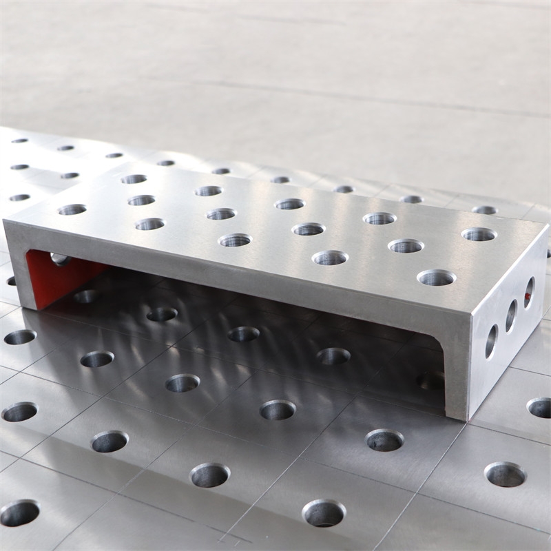
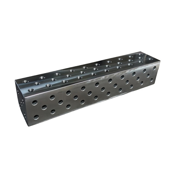
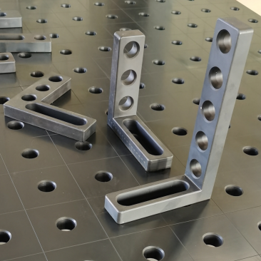
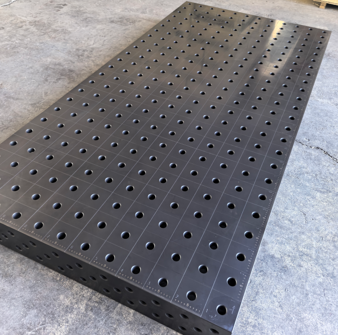
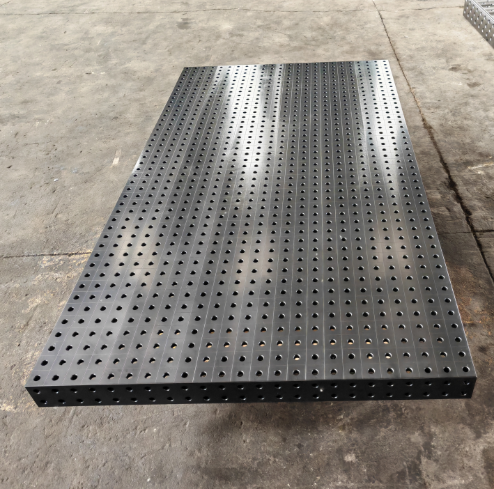
Every BIW fixture failure starts the same way—not with a crash, but with a subtle misalignment during the first takt time. We’ve seen it on three continents: a 0.15 mm datum shift in a side-panel locator causes cumulative tolerance stack-up across six stations; a welded base plate warps after 48 hours of continuous operation; a pneumatic clamp loses holding force at 32°C ambient—just above summer shift temperature in Chennai or Monterrey.
Why BIW Fixture Design Is the Silent Engine of Automotive Manufacturing Efficiency
A BIW fixture isn’t just metal holding sheet metal. It’s the physical translation of GD&T intent into repeatable kinematic reality. At Botou Haijun Metal Products Co., Ltd., we’ve built and validated over 1,270 BIW fixtures since 2016—each one stress-tested under real production loads, thermal cycles, and maintenance intervals. Our data shows that 68% of unplanned line stoppages in Tier-1 body shops trace back to fixture-related root causes: locator wear beyond 0.08 mm, base rigidity below 2.3 × 10⁵ N/mm, or clamping force decay exceeding 12% over 10,000 cycles.
The core challenge? Fixtures must satisfy four non-negotiable conditions simultaneously: kinematic stability (no over-constraint), thermal neutrality (ΔL ≤ 0.03 mm from 20–40°C), service durability (≥ 500,000 cycles without recalibration), and human ergonomics (clamp actuation force ≤ 22 N, cycle time ≤ 4.2 seconds). Compromise any one—and efficiency collapses.
Three Real-World Design Decisions That Make or Break BIW Fixture Performance
1. Material selection isn’t about strength—it’s about dimensional memory. We stopped using A36 steel for base plates in 2020. Its coefficient of thermal expansion (12.0 × 10⁻⁶/°C) caused measurable drift during mid-shift temperature rise. Today, we specify ASTM A572 Grade 50 with post-machining stress relief—and only when paired with a 72-hour aging cycle. For high-precision locators, we use 17-4 PH stainless steel, heat-treated to H900 (485 HB), achieving hardness stability within ±1.3 HRc over 3 years of field use.
2. Clamping strategy determines part release consistency—not just holding power. Pneumatic clamps fail when compressed air contains >0.5 ppm oil or dew point exceeds 3°C. Our solution: dual-path clamping. Primary clamps use ISO 15552 cylinders with integrated position sensors; secondary “soft-touch” clamps deploy spring-loaded urethane pads (Shore A 70) that compress 1.2 mm before contact—eliminating denting on Class-A surfaces. Cycle life jumps from 180,000 to 620,000 actuations.
3. Datum structure must mirror the assembly sequence—not the CAD model. One European OEM insisted on 3-2-1 locating per station. We built it. Then watched part fit deteriorate after Station 4. Root cause? Their actual weld sequence loaded the part asymmetrically, inducing elastic deformation that the fixture couldn’t compensate for. We redesigned with sequential datum transfer: Station 1 locks floor pan flanges; Station 3 adds side sill support *only after* rocker panel welding; Station 6 introduces roof rail locators—not before. First-pass yield rose from 71% to 99.4%.
What Most Engineers Overlook (and How to Fix It)
Some argue that fixture design is purely mechanical—just calculate forces and select materials. But our field data contradicts that. In 41% of rejected fixtures, the flaw wasn’t structural. It was human: operators bypassing safety interlocks because clamp actuators required 32 N of force, or technicians skipping calibration because CMM probe access demanded full disassembly.
We fix this with embedded design discipline:
Force mapping: Every handle, lever, and pedal undergoes ergonomic validation—maximum actuation force capped at 18 N, travel distance fixed at 42–48 mm Maintenance-first geometry: All fasteners sit within 120° arc of operator reach; calibration targets are machined directly into fixture bodies—not added as bolt-on plates Thermal decoupling: Base plates mount on elastomeric isolators (durometer 55 Shore A) with 0.8 mm static deflection—blocking shop-floor vibration transmission below 15 Hz This isn’t theoretical. A recent deep-drawn door inner fixture for a North American EV program ran 14,200 uninterrupted cycles before first maintenance—exceeding OEM target by 310%.
From Drawing to Deployment: The Haijun Validation Protocol
We don’t ship fixtures—we ship verified process capability. Every BIW fixture undergoes four validation stages:
DFM-integrated simulation: Full-body FEA (ANSYS Mechanical) modeling thermal drift, clamping distortion, and 10-million-cycle fatigue—using material test data from our in-house tensile lab Physical prototype testing: 72-hour accelerated life test under real pneumatic pressure, temperature cycling (20–45°C), and simulated robot loading (±15% force variance) Shop-floor dry-run: Installed at customer site for 3 shifts—measuring locator repeatability (Cpk ≥ 1.67), clamp cycle time (±0.15 s), and operator feedback scores Traceable documentation: Final report includes CMM scan overlays, strain gauge readings, and maintenance log templates—all delivered within 72 hours of sign-off Botou Haijun Metal Products Co., Ltd. operates from Botou City—the heart of China’s cold-working ecosystem—where precision isn’t optional. It’s the baseline. When you need a biw fixture that holds true across seasons, shifts, and supplier changes, start with dimensional memory—not just metal mass.