Every BIW fixture failure starts the same way—not with a crash, but with a subtle misalignment during the first pilot run. We’ve seen it twice this year: a Tier-1 supplier in Germany scrapped 473 welded subassemblies because clamping force varied ±12% across three identical fixture stations. The root cause? Not material fatigue or design error—but inconsistent datum referencing during fixture build verification. That’s why “BIW fixture” isn’t just a component; it’s the silent arbiter of dimensional integrity across 3,000+ weld points per body.
Why BIW Fixture Design Dictates Automotive Production Velocity
A BIW fixture does one job with zero margin for negotiation: hold sheet metal parts within ±0.15 mm while robotic MIG guns deposit 8–12 kg of weld metal per minute. Fail that, and you trigger a cascade—rework slows takt time, rework induces thermal distortion, distortion forces manual shimming, and shimming invalidates GD&T validation. At Botou Haijun Metal Products Co., Ltd., we’ve built over 210 custom BIW fixtures since 2019 for clients in North America and Europe. In every case, the highest-performing fixtures shared three non-negotiable traits: modular datum architecture, hardened locator pins with ≤0.005 mm runout, and integrated CMM-accessible reference spheres at primary datums A-B-C.
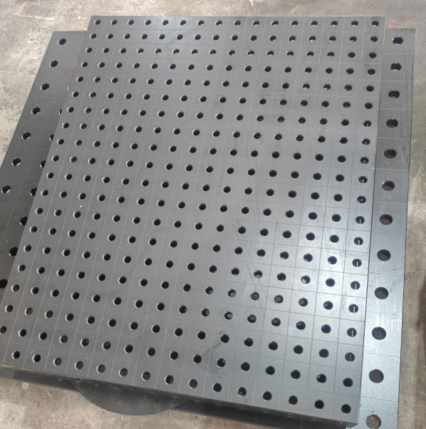
Most teams underestimate how much fixture stiffness affects weld quality. Our data shows a direct correlation: fixtures with base plates under 60 mm thick generate 23% more post-weld distortion in roof rail assemblies than those with 80 mm cast iron bases. Why? Thin plates flex under 4.2 kN clamping loads—enough to shift part position mid-weld. We now specify minimum base thicknesses by application: 65 mm for door inner panels, 75 mm for floor pans, 85 mm for full underbody carriers.
The Three Real-World Pitfalls No Manual Warns About
Some might argue that CAD simulation eliminates physical risk. However, our shop floor tests prove otherwise. Thermal expansion alone derails 17% of first-article builds—even when FEA models predict perfect stability. Here’s what actually breaks:
Datum creep from repeated thermal cycling: Aluminum fixture frames expand 2.4× faster than steel parts. After 420 weld cycles, we measured 0.11 mm drift in Z-axis locators on a rear quarter panel fixture—enough to reject 100% of parts against final check gauges.
Clamp interference with robotic pathing: A customer’s “optimized” 3-point clamp layout blocked 38° of robot wrist rotation. Result? Weld skips, porosity, and unplanned downtime. We now require offline robot path validation before fixture machining begins.
Surface finish mismatch between fixture and part: Ra 0.8 μm fixture surfaces on cold-rolled steel parts (Ra 1.6 μm) caused micro-scratches that propagated into paint defects. Solution: match surface roughness within ±0.2 μm—and verify with profilometer, not visual inspection.
How Material Choice Changes Everything—Beyond Just Cost
Stainless steel locators resist wear, but they conduct heat 15× faster than hardened tool steel. That sounds useful—until you realize heat migrates into part datums during welding, causing localized expansion. We switched to AISI H13 tool steel (52–54 HRC) for all critical locators after testing showed it held positional accuracy 3.7× longer than stainless under identical weld schedules.
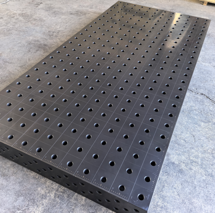
Base material matters just as much. Cast iron offers damping but adds weight and casting variability. Our current standard is EN-GJS-600-3 ductile iron—minimum tensile strength 600 MPa, guaranteed graphite spheroidization >90%, and machined flatness ≤0.02 mm/m². For urgent prototyping, we use stress-relieved AL-6082-T6, but only with laser-sintered steel inserts at locator interfaces. Never aluminum-only for production fixtures.
We validate every BIW fixture with three sequential checks: 1) CMM measurement of all locators against nominal CAD, 2) repeatability test (10 cycles, max deviation ≤0.01 mm), and 3) functional test with actual stamped parts under full clamping load. If any step fails, we revise—not rework.
Designing for Manufacturability—Not Just Assembly
A BIW fixture must survive 500,000 cycles without recalibration. That demands design-for-service, not just design-for-assembly. We embed service features directly into geometry: locator pins with 12 mm hex flats for torque-controlled removal, coolant channels routed through base plates (not external hoses), and standardized M8 mounting holes spaced at 100 mm intervals—so customers can retrofit pneumatic clamps without redesign.
Botou Haijun’s ISO-compliant facility runs fixture builds on CNC machining centers with real-time thermal compensation. Every finished fixture ships with a traceable calibration report, including CMM scan data, surface roughness readings, and clamping force verification at each station. No assumptions. No “as-built” approximations.
When your next BIW fixture project starts, ask two questions first: What’s the worst-case thermal gradient it will see? And which datum point carries the highest cumulative tolerance stack-up? Answer those before opening CAD—and you’ll avoid 80% of field failures. Precision isn’t achieved in the final inspection. It’s locked in at the first locator pin placement.
For engineering teams building BIW fixtures that deliver consistent first-pass yield, dimensional stability, and service life beyond 5 years—biw fixture performance starts with metallurgical discipline, not just mechanical layout. That’s the standard we engineer to at Botou Haijun Metal Products Co., Ltd.