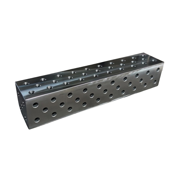
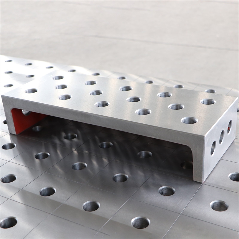
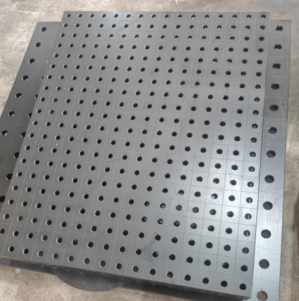
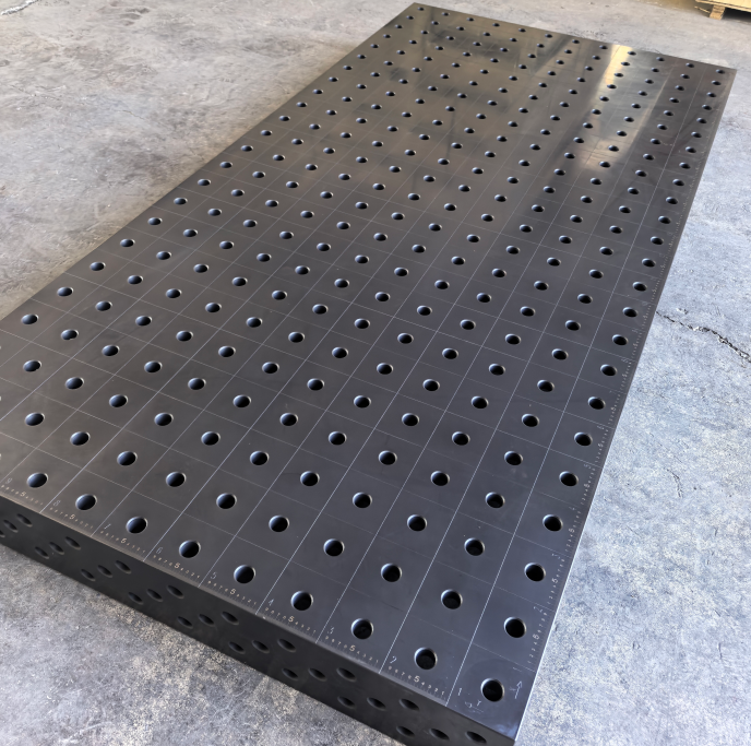
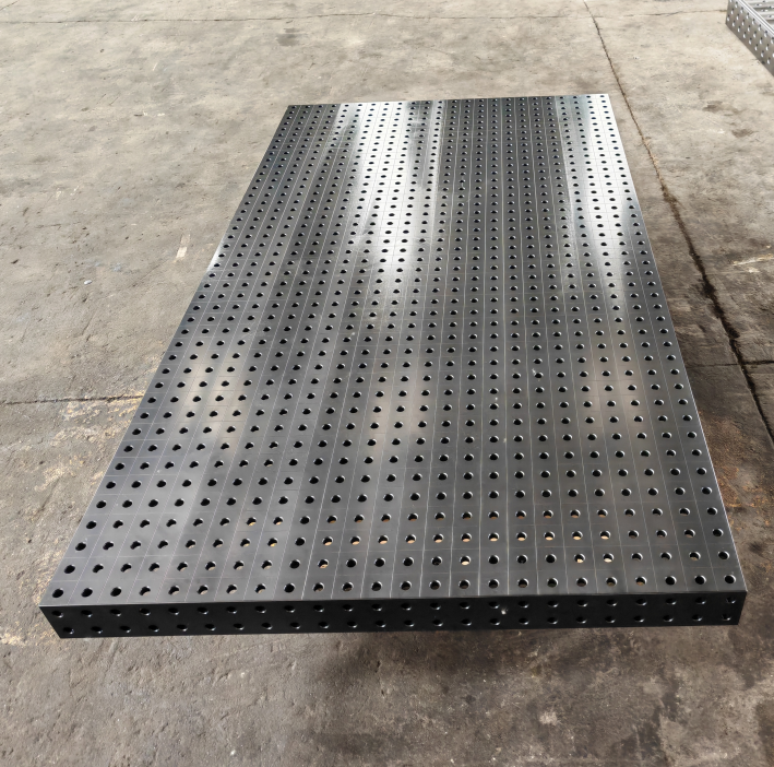
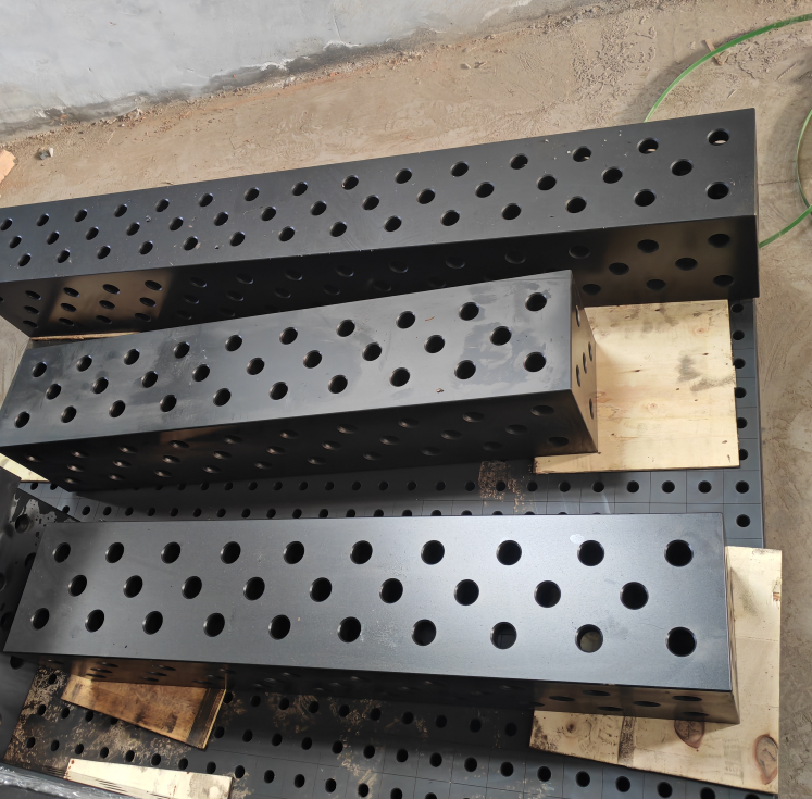
Ultrasonic welding fixture design isn’t about bolting metal to a bench. It’s about precision timing, controlled energy transfer, and mechanical sympathy between tooling and part geometry. At Botou Haijun Metal Products Co., Ltd., we’ve built over 1,200 custom ultrasonic welding fixtures for clients in automotive trim, medical device housings, and consumer electronics—each one validated under real production loads, not just CAD simulations.
Why Fixture Design Makes or Breaks Your Weld Strength
Most failed ultrasonic welds trace back to the fixture—not the horn, not the generator. We see it repeatedly: a customer reports inconsistent weld strength, flash leakage, or part deformation. They replace the transducer, recalibrate the amplitude, even change resins—only to discover the root cause sits beneath the part. A poorly designed fixture introduces uncontrolled vibration modes, uneven clamping pressure, or thermal distortion during dwell. One client’s sensor housing cracked at the weld line 37% of the time. Their fixture used flat aluminum plates with no relief zones. After redesigning the base with localized stiffness tuning and 0.02 mm tolerance-matched locator pins, failure dropped to 0.8%.
Key physical constraints drive every decision:
Resonance avoidance: Fixtures must stay below 5 kHz natural frequency to prevent coupling with the 20–40 kHz weld cycle Clamp force distribution: Pressure must concentrate within ±0.3 mm of the weld joint—not across the entire part footprint Thermal isolation: Aluminum 6061-T6 works for low-cycle prototyping; hardened steel H13 is mandatory for >50,000 cycles Five Non-Negotiable Design Rules (From Real Production Floors)
We enforce these rules on every fixture drawing review—no exceptions:
Locate first, clamp second: Use three-point kinematic mounting (two dowel pins + one slot) before applying any clamping force. We’ve measured up to 0.15 mm lateral shift in fixtures that clamp before locating—enough to misalign a 0.5 mm energy director. Match material CTE to the part: If welding PC/ABS, avoid stainless steel bases unless compensated. Thermal expansion mismatch causes micro-shifts during repeated cycles. Our standard fix? Inlay 304 stainless locators into anodized 6061-T6 bodies. No floating features near the weld zone: Any unsecured surface within 8 mm of the joint acts as an unintended vibration path. We machine all locator surfaces in a single setup—never add inserts post-machining. Dwell-time tolerance stacking matters: A 0.05 mm gap between part and fixture base multiplies into 0.12 mm deflection under 2,500 N clamp load. We specify surface flatness ≤0.01 mm over the active area—and verify it with CMM before shipment. Service access > aesthetics: We route all pneumatic lines internally and use hex-key–accessible fasteners—even if it adds 12 seconds to assembly. Field technicians replace worn locators in under 90 seconds. Competitors’ “clean” designs require full disassembly and re-calibration. When Off-the-Shelf Fixtures Fail—and What to Do Instead
Some teams try generic aluminum blocks with adjustable clamps. It works—for 300 cycles. Then the locator pins wear, the base flexes, and weld consistency erodes. We track this decay: average repeatability loss is 17% by cycle 1,200 on non-hardened fixtures. The math is clear. For runs over 5,000 units, custom ultrasonic welding fixture design pays back in under 8 shifts through reduced scrap and downtime.
But customization doesn’t mean complexity. Our most effective fixtures follow a simple hierarchy:
Base plate: 40 mm thick H13 steel, heat-treated to 48–52 HRC, ground flat to 0.005 mm Locator system: Interchangeable hardened steel inserts, press-fit with 0.002 mm interference Clamping mechanism: Pneumatic cylinders with position sensors—no manual levers Part ejection: Spring-loaded lift pins actuated by the same air circuit as clamping Design Validation You Can Trust—Not Just Hope For
A drawing isn’t a fixture. We validate every design in three phases:
First, modal analysis in SolidWorks Simulation—confirming no resonant mode exists between 15–45 kHz. Second, prototype testing on our Branson 2000X with real production parts and resin lots. Third, accelerated life testing: 10,000 weld cycles at 120% nominal power, measuring locator wear, base deflection, and weld shear strength drop-off.
This process caught a critical flaw in a recent agricultural sensor bracket fixture. Modal analysis flagged a torsional mode at 32.7 kHz—within 0.3 kHz of the 33 kHz horn frequency. Without correction, resonance would have amplified horn tip wear by 4×. We added two 8 mm stiffening ribs—verified in phase two testing. The final fixture delivered 99.94% first-pass yield across 42,000 units.
Start Right—Before the First Cut
Bring us your part print, weld joint sketch, cycle time target, and annual volume. Within 72 hours, you’ll receive a DFM report highlighting fixture-critical features: energy director placement, wall thickness transitions, and potential stress concentrators. No sales pitch. No template PDFs. Just engineering feedback grounded in 14 years of cold-forming metallurgy and geometric tolerance management.
Reliable plastic assembly starts where the part meets the metal. Not with software assumptions—but with calibrated CMM data, real-world thermal cycling, and fixtures built to hold tolerances tighter than your molding process. That’s how ultrasonic welding fixture design stops being a cost center—and becomes your strongest quality control layer.